February 1, 2026 · Science Explainer · DFM Engineering Note
How Injection-Molding Shrinkage Impacts Part Fit
Injection-molding shrinkage directly affects part fit, and many risks can be reduced during the DFM stage.
If shrinkage is not compensated in mold design, final parts may show gap, stress, or snap-fit instability. Early DFM review of wall thickness and gate position is critical.
Why Shrinkage Becomes Fit Risk
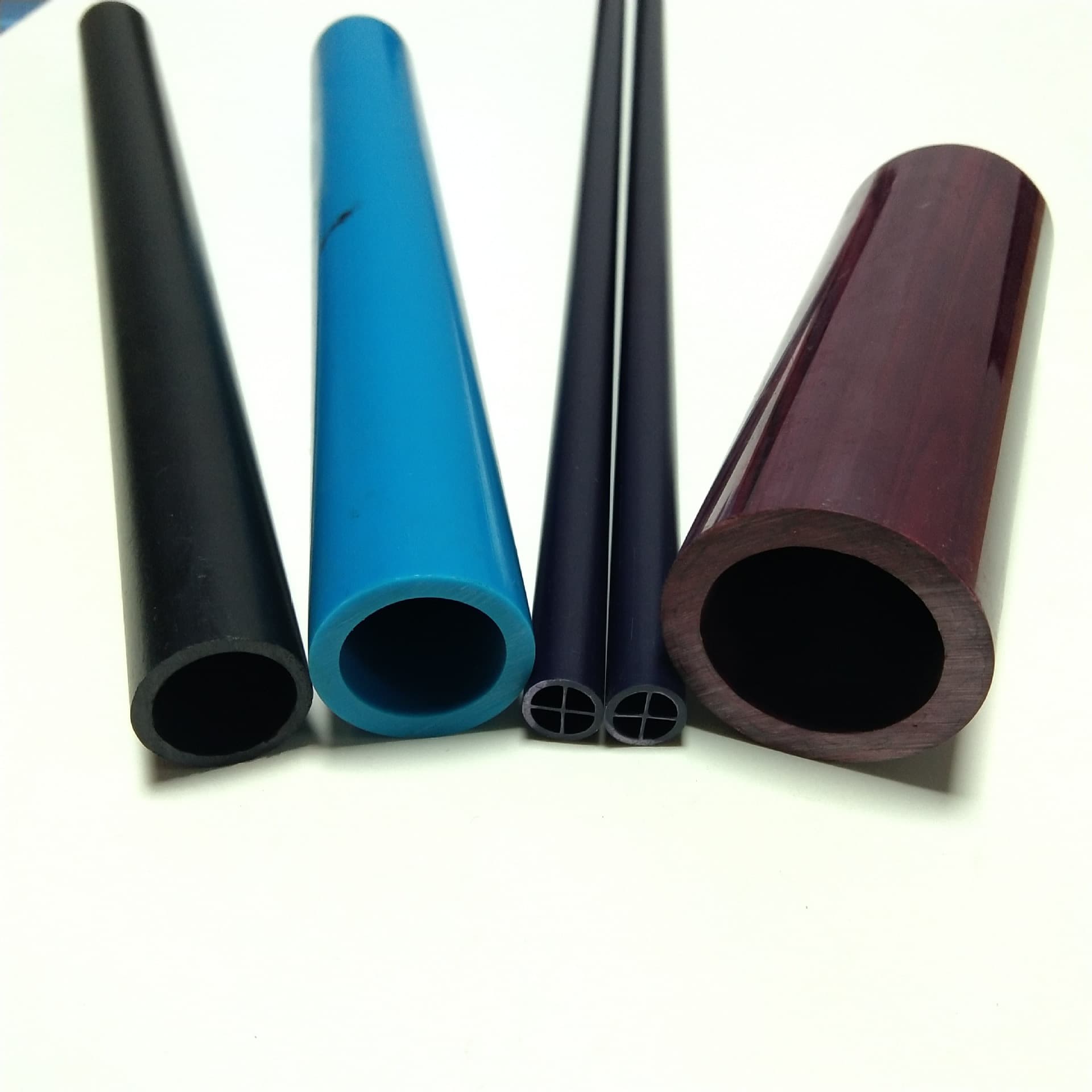
Uneven wall thickness and non-optimized gate position can produce local shrinkage differences, leading to gap or stress during assembly.
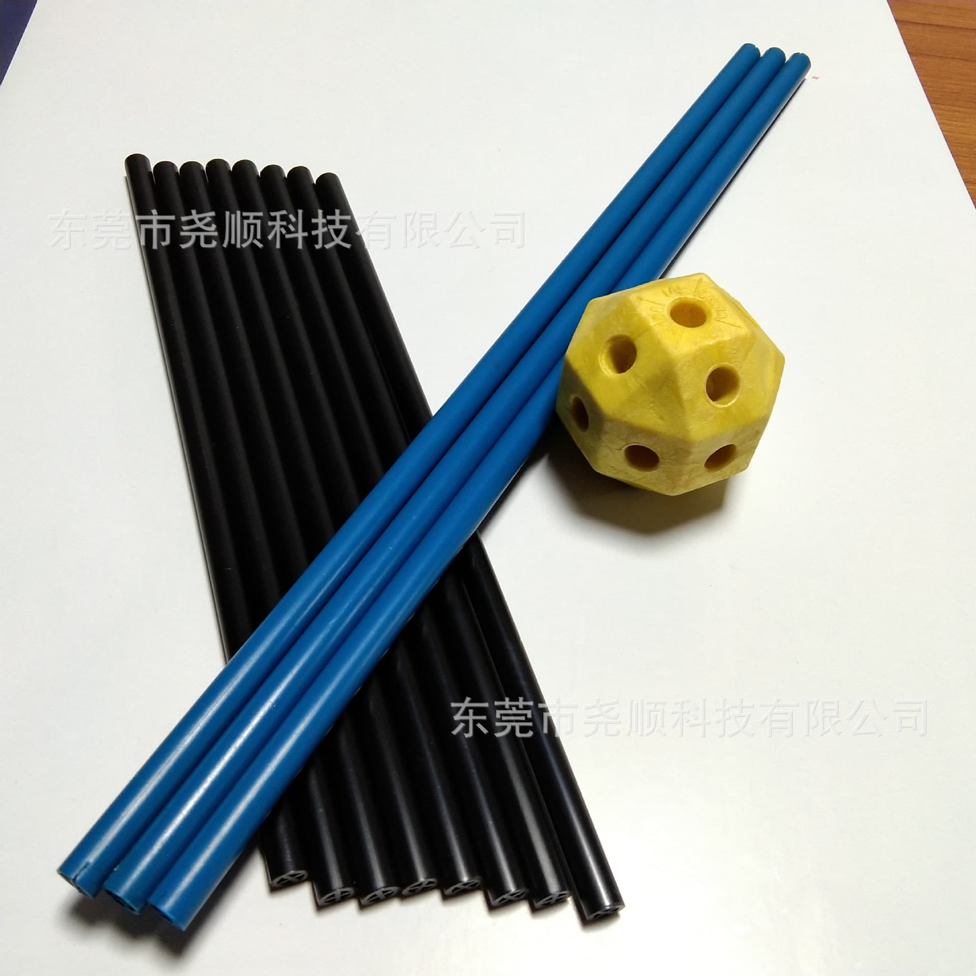
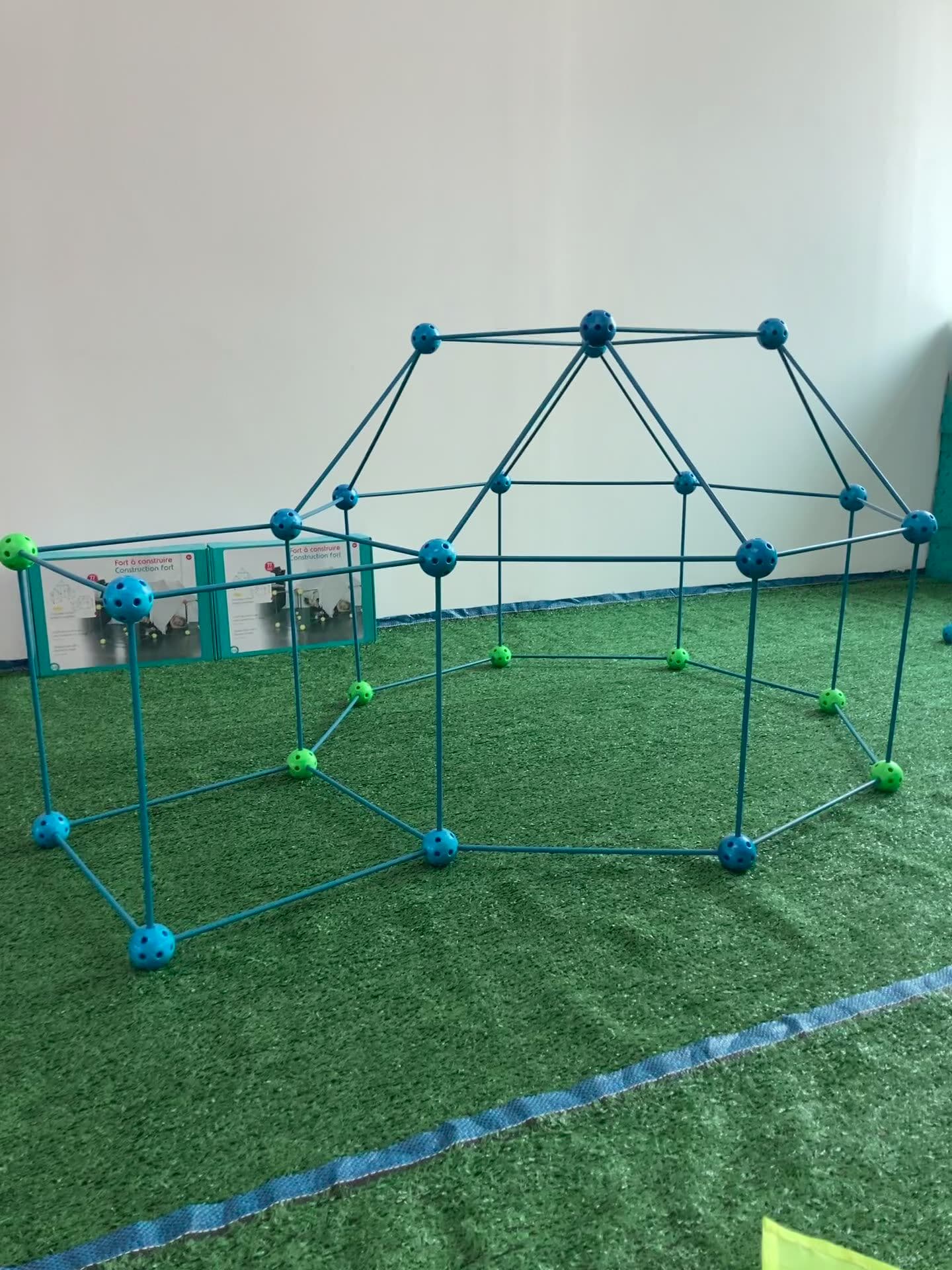
In interlocking components, small dimensional drift can directly change insertion force and long-term stability perception.
DFM Compensation Practices
Common compensation includes local wall tuning, rib transition optimization, and gate redesign with mold-flow evidence.
A short pilot with dimensional map is recommended before final release to verify actual shrink response by cavity.
Shrinkage Control Checklist
1. Review wall thickness and gate plan in DFM kickoff.
2. Use mold-flow evidence for compensation decisions.
3. Validate cavity-level dimensions in pilot lot.
Source Note
Prepared from Yaoshun toy, tube, and equipment project practices plus public product modules. Snapshot date: April 12, 2026.